Hardware
I followed the schematic provided by the folks at RANDOM DATA.

Testing the circuit on a breadboard.

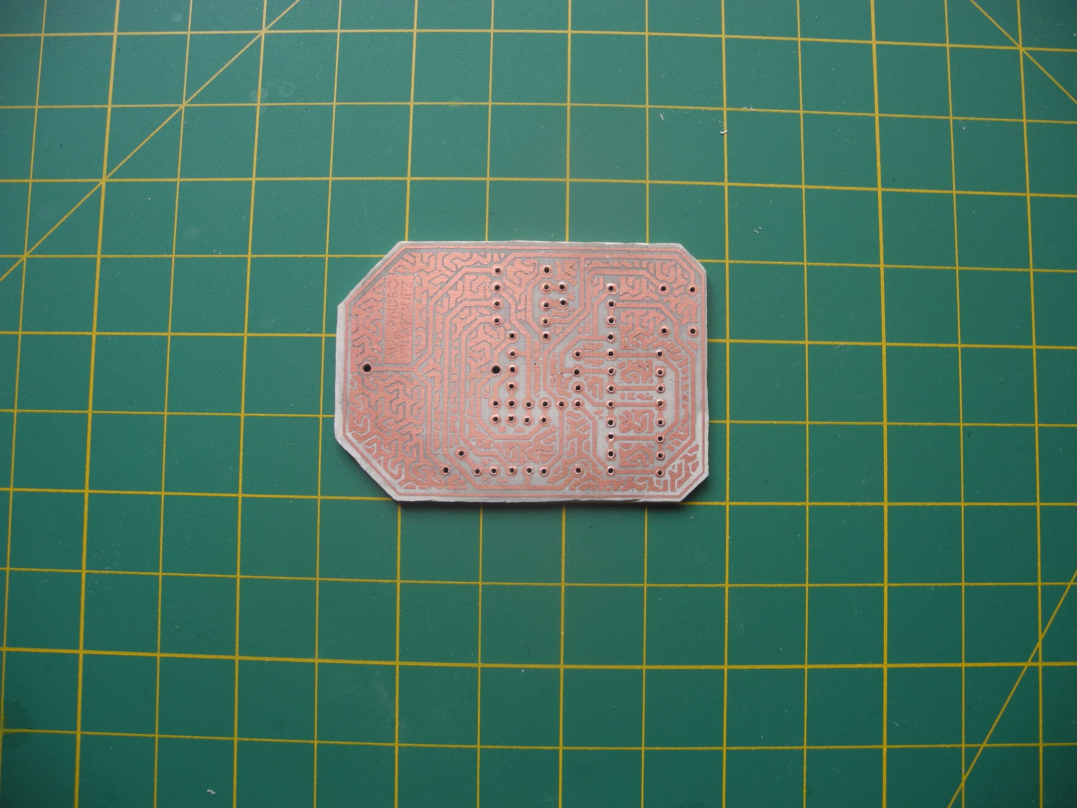
The design has a single sided PCB, since it was easier for me to etch it.
Here’s a picture of the etched board, with holes drilled (files on GitHub).

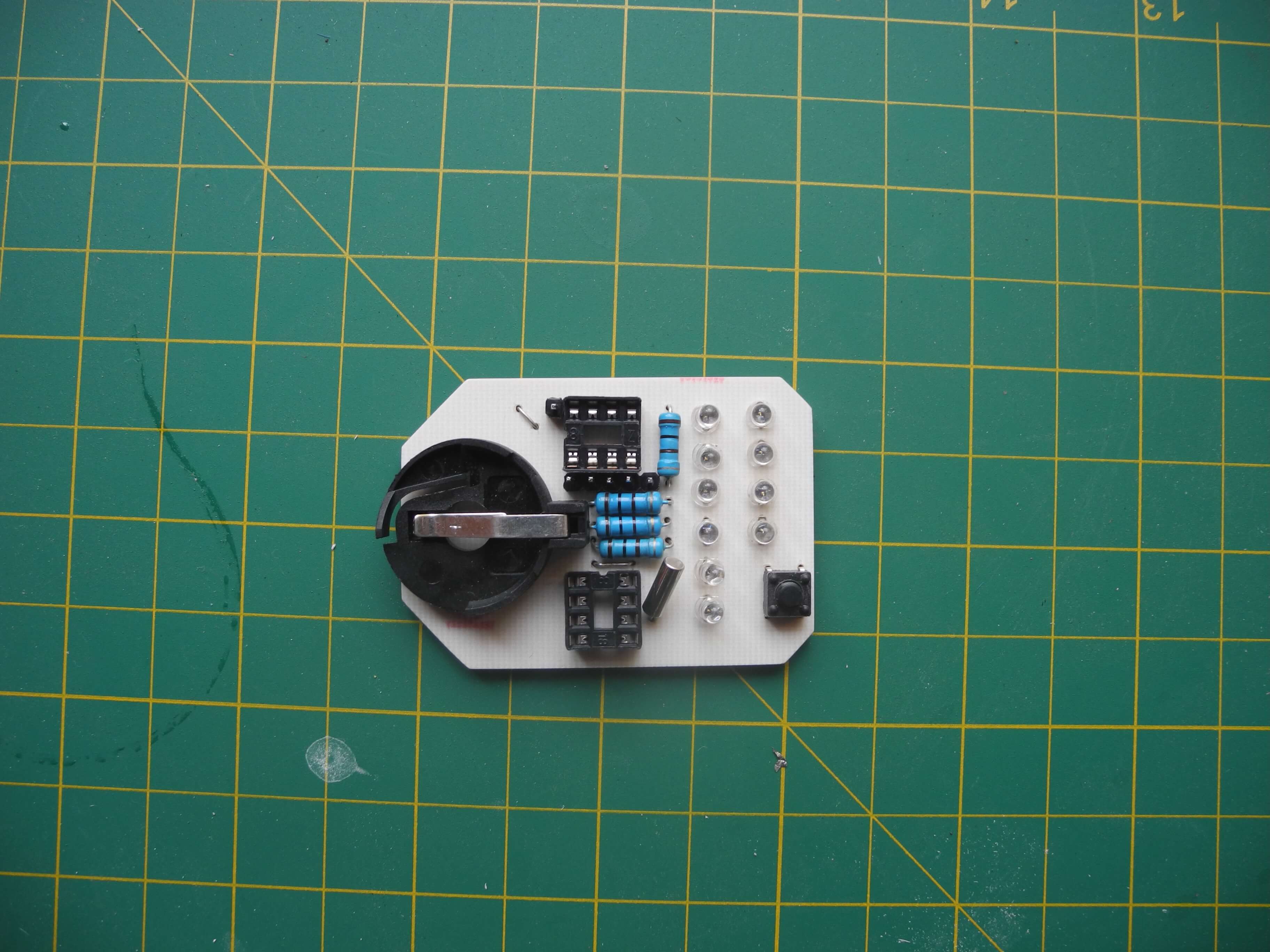
The (really badly) soldered board.

The front.

Since I wanted a different component arrangement than that of the RandomWatch I used Fritzing to create the PCB file to print. I chose it over other software like KiCAD because I had used it before to create breadboard diagrams and I did’t want to invest the time to learn a new tool.
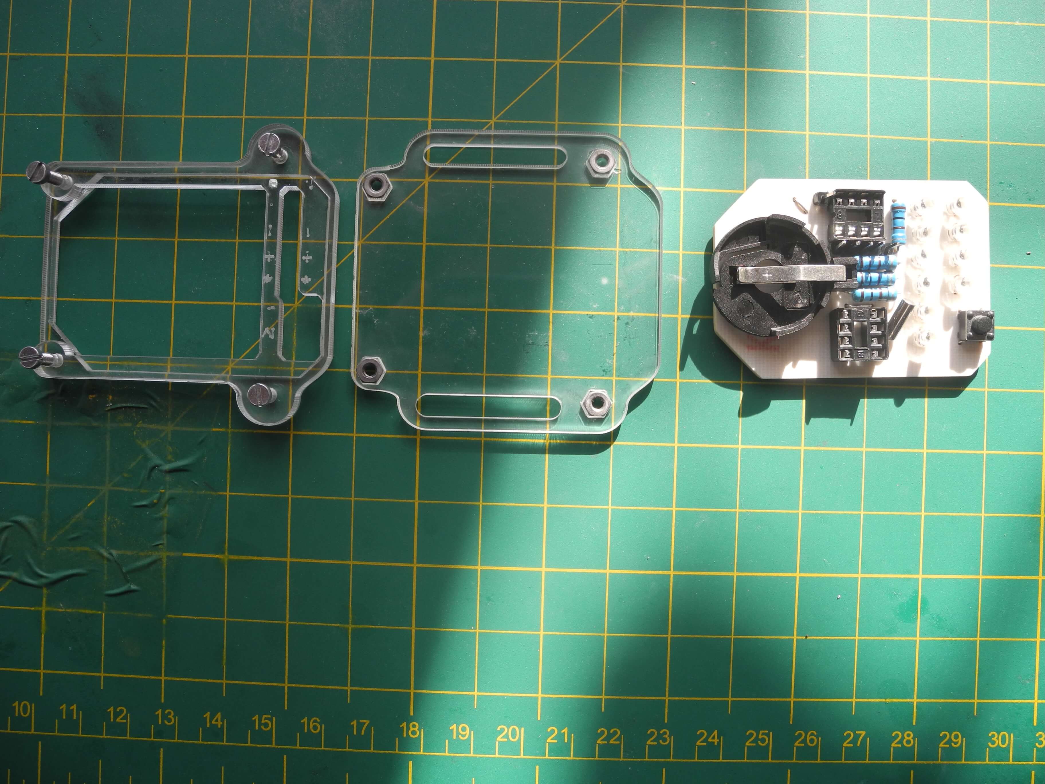
I glued the nuts to the back of the case to be able to hold it together with four screws.

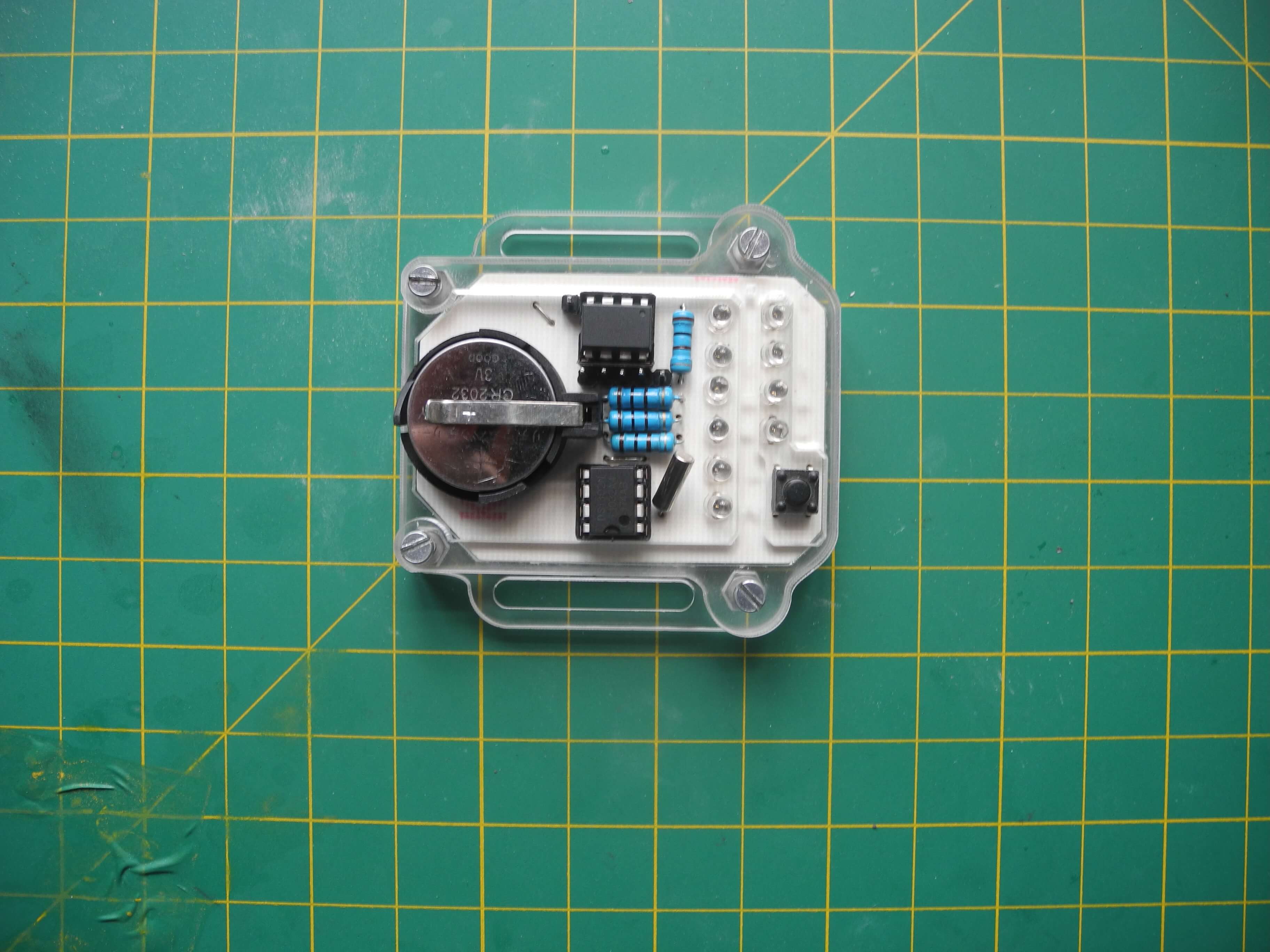
The populated case.
